Deploying Wallarm from GCP Machine Image
This article provides instructions for deploying Wallarm on GCP in-line using the official Machine Image.
The image is based on Debian and the NGINX version provided by Debian. Currently, the latest image uses Debian 12, which includes NGINX stable 1.22.1.
Use cases
Among all supported Wallarm deployment options, GCP Machine Image is recommended for Wallarm deployment in these use cases:
-
Your existing infrastructure resides on GCP.
-
You aim to deploy a security solution as a separate cloud instance, rather than installing it directly on frontend systems like NGINX.
Requirements
-
A GCP account
-
Access to the account with the Administrator role in Wallarm Console for the US Cloud or EU Cloud
-
Access to
https://us1.api.wallarm.com:444for working with US Wallarm Cloud or tohttps://api.wallarm.com:444for working with EU Wallarm Cloud. If access can be configured only via the proxy server, then use the instructions -
Access to the IP addresses below for downloading updates to attack detection rules and API specifications, as well as retrieving precise IPs for your allowlisted, denylisted, or graylisted countries, regions, or data centers
-
Executing all commands on a Wallarm instance as a superuser (e.g.
root)
1. Launch a filtering node instance
Launch the instance via the Google Cloud UI
To launch the filtering node instance via the Google Cloud UI, please open the Wallarm node image on the Google Cloud Marketplace and click GET STARTED.
The instance will launch with a preinstalled filtering node. To see detailed information on launching instances in the Google Cloud, please proceed to the official Google Cloud Platform documentation.
Launch the instance via Terraform or other tools
When using a tool like Terraform to launch the filtering node instance using Wallarm GCP image, you may need to provide the name of this image in the Terraform configuration.
-
Image name has the following format:
-
To launch the instance with the filtering node version 5.x, please use the following image name:
To get the image name, you can also follow these steps:
-
Install Google Cloud SDK.
-
Execute the command
gcloud compute images listwith the following parameters: -
Copy the version value from the name of the latest available image and paste the copied value into the provided image name format. For example, the filtering node version 4.10 image will have the following name:
2. Configure the filtering node instance
Perform the following actions to configure the launched filtering node instance:
-
Navigate to the VM instances page in the Compute Engine section of the menu.
-
Select the launched filtering node instance and click the Edit button.
-
Allow the required types of incoming traffic by ticking the corresponding checkboxes in the Firewalls setting.
-
If necessary, you can restrict connecting to the instance with the project SSH keys and use a custom SSH key pair for connecting to this instance. To do this, perform the following actions:
- Tick the Block project-wide checkbox in the SSH Keys setting.
- Click the Show and edit button in the SSH Keys setting to expand the field for entering an SSH key.
-
Generate a pair of public and private SSH keys. For example, you can use the
ssh-keygenandPuTTYgenutilities.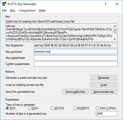
-
Copy an open key in OpenSSH format from the interface of the used key generator (in the current example, the generated public key should be copied from the Public key for pasting into OpenSSH authorized_keys file area of the PuTTYgen interface) and paste it into the field containing the Enter entire key data hint.
- Save the private key. It will be required for connecting to the configured instance in the future.
-
Click the Save button at the bottom of the page to apply the changes.
3. Connect to the filtering node instance via SSH
To see detailed information about ways of connecting to instances, proceed to this link.
Connecting to the instance via a custom private key
If during base instance creation process you have enabled connection to the instance via a custom SSH key pair, make sure you have access to the private key from this key pair.
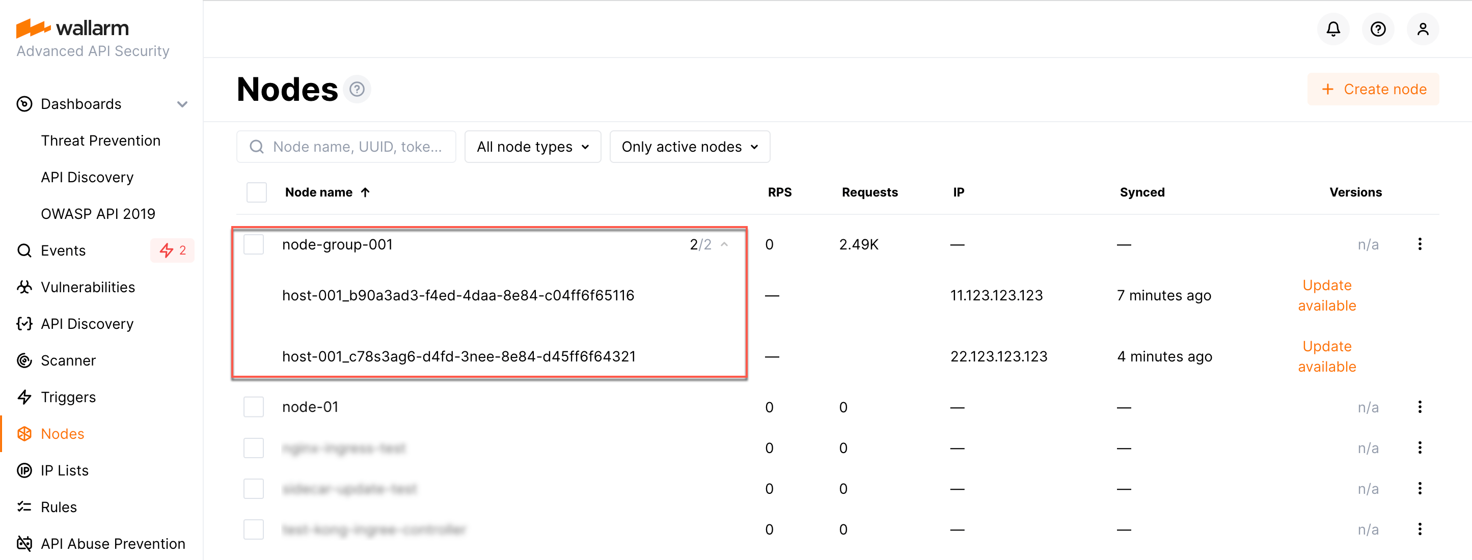
4. Generate a token to connect an instance to the Wallarm Cloud
The local Wallarm filtering node needs to connect with the Wallarm Cloud using a Wallarm token of the appropriate type. An API token allows you to create a node group in the Wallarm Console UI, which helps in organizing your node instances effectively.
Generate a token as follows:
5. Connect the filtering node to the Wallarm Cloud
The cloud instance's node connects to the Cloud via the cloud-init.py script. This script registers the node with the Wallarm Cloud using a provided token, globally sets it to the monitoring mode, and sets up the node to forward legitimate traffic based on the --proxy-pass flag. Restarting NGINX finalizes the setup.
Run the cloud-init.py script on the instance created from the cloud image as follows:
-
WALLARM_LABELS='group=<GROUP>'sets a node group name (existing, or, if does not exist, it will be created). It is only applied if using an API token. -
<TOKEN>is the copied value of the token. -
<PROXY_ADDRESS>is an address for Wallarm node to proxy legitimate traffic to. It can be an IP of an application instance, load balancer, or DNS name, etc., depending on your architecture.
6. Configure sending traffic to the Wallarm instance
Update targets of your load balancer to send traffic to the Wallarm instance. For details, please refer to the documentation on your load balancer.
7. Test the Wallarm operation
-
The request with test Path Traversal attack to an address of either the load balancer or the machine with the Wallarm node:
-
Open Wallarm Console → Attacks section in the US Cloud or EU Cloud and make sure the attack is displayed in the list.
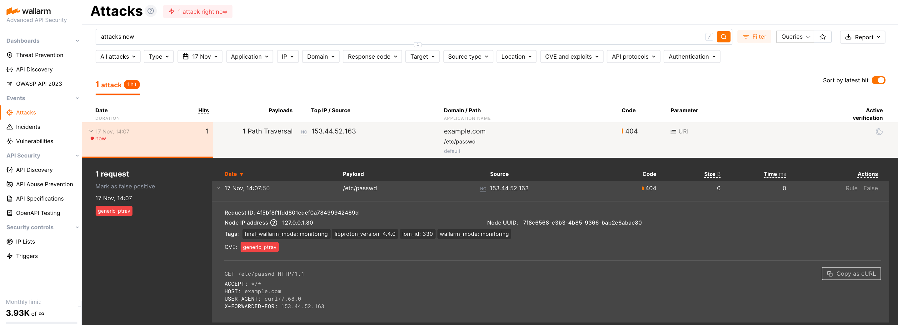
Since Wallarm operates in the monitoring mode, the Wallarm node does not block the attack but registers it.
-
Optionally, test other aspects of the node functioning.
8. Fine-tune the deployed solution
The deployment is now complete. The filtering node may require some additional configuration after deployment.
Wallarm settings are defined using the NGINX directives or the Wallarm Console UI. Directives should be set in the following files on the Wallarm instance:
-
/etc/nginx/sites-enabled/defaultdefines the configuration of NGINX -
/etc/nginx/conf.d/wallarm.confdefines the global configuration of Wallarm filtering node -
/etc/nginx/conf.d/wallarm-status.confdefines the filtering node monitoring service configuration -
/opt/wallarm/wstore/wstore.yamlwith the postanalytics service (wstore) settings
You can modify the listed files or create your own configuration files to define the operation of NGINX and Wallarm. It is recommended to create a separate configuration file with the server block for each group of the domains that should be processed in the same way (e.g. example.com.conf). To see detailed information about working with NGINX configuration files, proceed to the official NGINX documentation.
Creating a configuration file
When creating a custom configuration file, make sure that NGINX listens to the incoming connections on the free port.
Below there are a few of the typical settings that you can apply if needed:
To apply the settings, restart NGINX on the Wallarm instance:
Each configuration file change requires NGINX to be restarted to apply it.