Setting up incoming request balancing on GCP
Now that you have a configured managed instance group with enabled auto scaling, you need to create and configure a Load Balancer that distributes incoming HTTP and HTTPS connections between several filtering nodes from the instance group.
You can configure the following types of Load Balancers on the Google Cloud Platform:
-
HTTP(S) Load Balancer
-
TCP Load Balancer
-
UDP Load Balancer
The differences between Load Balancers
For detailed information about the differences between Load Balancers, proceed to this link.
This document demonstrates how to configure and use the TCP Load Balancer that distributes traffic at the transport level of the OSI/ISO network model.
Create a TCP Load Balancer for your instance group by completing the following actions:
-
Navigate to the Load balancing page in the Network services section of the menu and click the Create load balancer button.
-
Click the Start configuration button on the TCP load balancing card.
-
Select the required options in the following settings:
-
Select the From Internet to my VMs option in the Internet facing or internal only setting so that the load balancer will control incoming requests from clients to your server.
-
Select the Single region only option in the Multiple regions or single region setting.
Traffic balancing for resources located in different regions
This guide describes the configuration of the load balancer for one instance group located in a single region.
In the case of balancing traffic for several resources located in multiple regions, select the Multiple regions (or not sure yet) option.
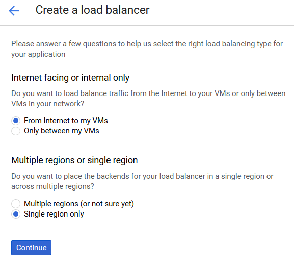
Click the Continue button.
-
-
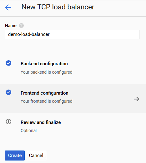
Enter the load balancer name into the Name field.
-
Click the Backend configuration to use the created instance group as the backend to which the load balancer will route the incoming requests.
-
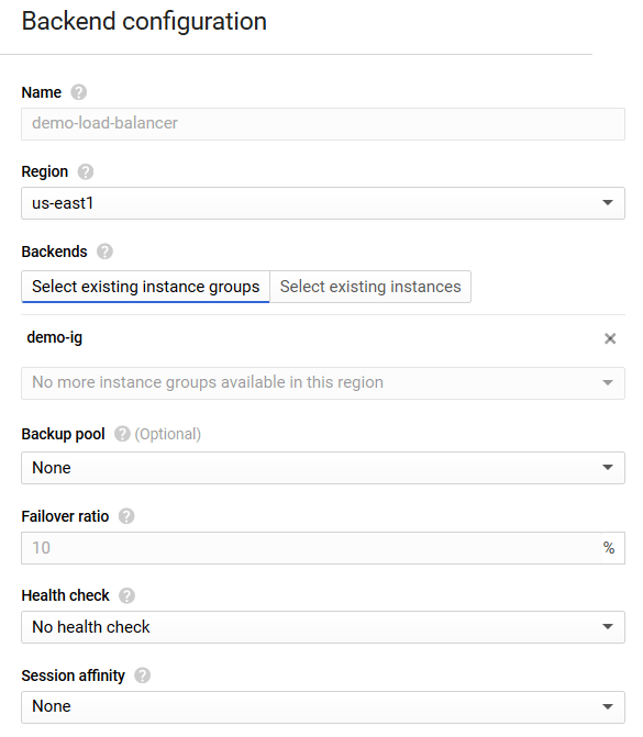
Fill in the form with the following data:
-
Select the region where the instance group is located from the Region drop-down list.
-
Navigate to the Select existing instance groups tab in the Backends setting and select the name of the instance group from the Add an instance group drop-down list.
-
If necessary, specify the backup pool by selecting the Create a backup pool option from the Backup Pool drop-down list.
Using a backup pool
A backup pool processes the requests if the instance group selected in the previous setting is unavailable. For detailed information about configuring a backup pool, proceed to this link.
This document does not describe the backup pool configuration.
-
If necessary, configure the group instances availability checkup by selecting the Create a health check option in the Health check drop-down list. For detailed information about the machine availability checkup, proceed to this link.
The availability checkup
The availability checkup is not configured in the scope of this document. Thus, here the No health check option is selected in the Health check drop-down list.
-
If necessary, configure the method of choosing an instance for request processing by selecting the corresponding option in the Session affinity drop-down list. Detailed information about selecting an instance for request processing is available at this link.
Configuring a method of choosing an instance
The method of choosing an instance for request processing is not in the scope of this document. Thus, here the None option is selected in the Session affinity drop-down list.
-
-
Click the Frontend configuration button to specify the IP addresses and ports to which clients will send their requests.
-
Fill in the form for new IP addresses and ports creation with the required data:
-
If necessary, enter the new IP address and port pair's name into the Name field.
-
Select the required network service tier in the Network Service Tier setting. For detailed information about network service tiers, proceed to this link;
-
Select the IP address where the load balancer will receive requests from the IP drop-down list.
-
Select the Ephemeral option if you want the load balancer to obtain a new IP address upon each virtual machine startup.
-
Select the Create IP address option to generate a static IP address for your load balancer.
In the form that appears, enter the name of the new IP address into the Name field and click the Reserve button.
-
-
Enter the port where the load balancer will receive requests in the Port field.
Choosing the port
In this document, port
80is specified for receiving requests via the HTTP protocol.
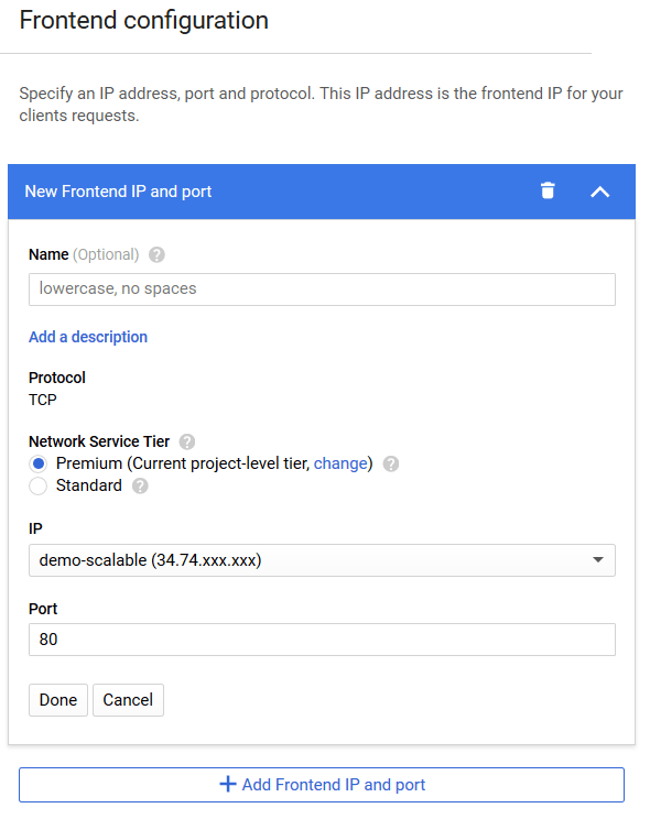
Click the Done button to create the configured IP address and port pair.
Required frontend ports
In this document, the balancer is configured for receiving requests via the HTTP protocol. If your instance group receives requests via the HTTPS protocol, create another IP address and port pair that specifies port
443. -
-
Click the Create button to create the configured load balancer.
Wait until the load balancer creation process is finished and the load balancer connects to the instance group that you created earlier.
Because the created TCP balancer uses the Backend service (which works together with the backend created for your instance group), the instance group requires no configuration modifications for the balancer to connect to it.
Now the dynamically scaling set of the Wallarm filtering nodes will process the incoming traffic to your application.
To check the deployed filtering nodes operation, perform the following steps:
-
Make sure that your application is accessible through the load balancer and the Wallarm filtering nodes by referring to the balancer IP address or domain name using your browser.
-
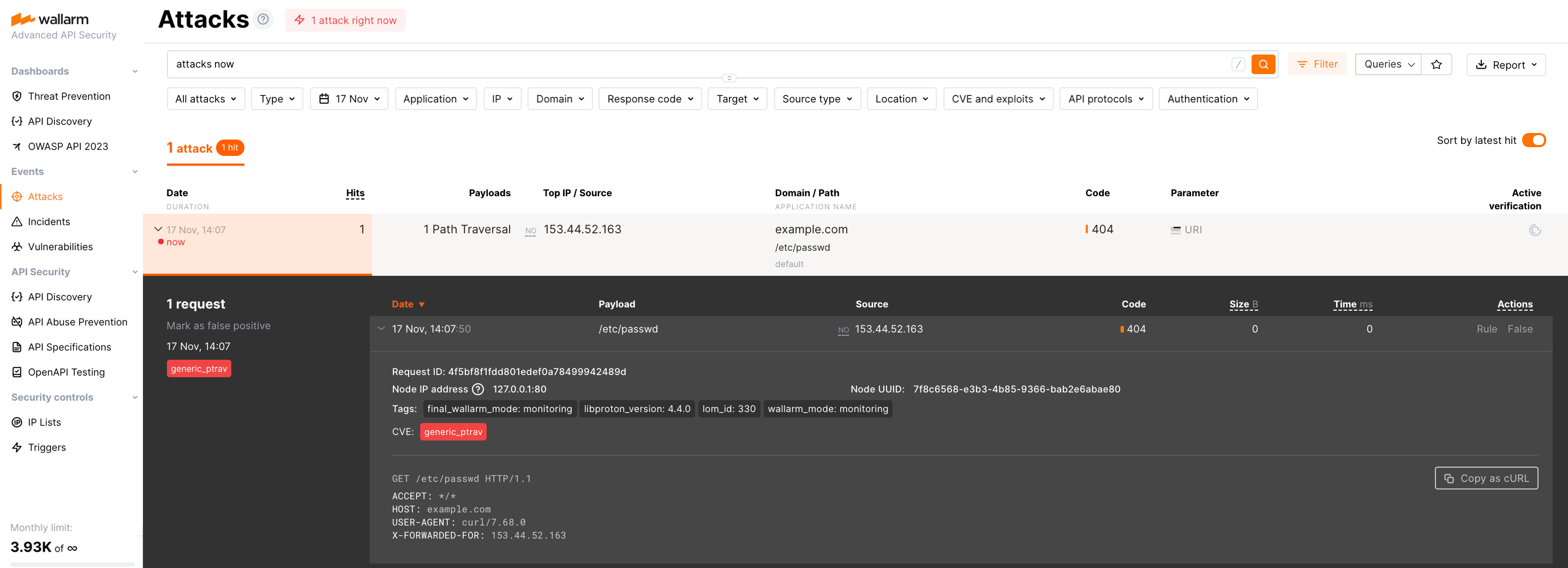
Make sure that the Wallarm services protect your application by performing a test attack.